The virtual laboratory was developed to simulate gyroscope nutation and precession. The program's interactive abilities allow doing a large number of virtual experiments to study the gyroscope behavior. Dynamic visualization of the gyroscope movement, supplemented by graphs, allows you to analyze the processes in detail. You can observe and investigate various gyroscope motions as unidirectional precession, looping precession and cuspidal motion. An image of the trajectory of the gyroscope axis end accompanies real-time visualization of the gyroscope motion. All physical processes are modeled without friction at the point of fixing the axis and air resistance.
Use
the left mouse button to rotate the camera.
Use
the mouse wheel to zoom in and out of the camera.
The
menu item «Graphs» includes graphs of the angle $$\theta$$ as a function of $$\varphi$$ and as a function of time, as well as graphs of the kinetic,
potential, and total energies of the gyroscope as functions of time.
The
menu item «About» contains the user’s manual, theoretical information and information about the developers of the software product.
The
program interface is located on the right side of the window, which is used for the main interaction with the installation.
The
«Start» and «Pause» buttons start and stop the process of dynamic visuali-zation in real time.
You
can completely stop the experiment by clicking the "Reset" button. The installation and all its parameters will return to the initial state.
Under the «Start», «Pause» and «Reset» buttons there are six sliders:
The
first slider is responsible for changing the distance from the vertical axis to the disk. The interval of change is from 0.15 to 0.2 m. The step of
change is 0.01 m.
The
second slider is responsible for changing the mass of the disk. The interval of change is from 0.1 to 2 kg. The step of change is 0.1 kg.
The
third slider is responsible for changing the radius of the disk. The interval of change is from 0.05 to 0.08 m. The step of change is 0.01 m.
The
fourth slider is responsible for changing the rotation speed of the disk. The interval of change is from 500 to 1000 rad/s. The step of change is 1
rad/s.
The
fifth slider is responsible for changing the initial precession speed. The interval of change is from -3 to 3 rad/s. The step of change is 0.1
rad/s.
The
sixth slider is responsible for changing the inclination angle in relation to the vertical axis. The interval of change is from 45 to 90 degrees.
The step of change is 1 degree.
The
presence of a virtual timer makes it possible to determine the current time of the experiment. Time is displayed in minutes, seconds, and
milliseconds.
You
can pause the time measurement by clicking the «Pause» button located next to the «Start» button. To continue measuring, just click the «Start»
button again.
You
can stop the time measurement completely by clicking the «Reset» button located next to the «Pause» button. When you click the button, the time is
reset to zero.
You
can start the timer together with the gyroscope or separately. To start the timer together with the gyroscope, click on the checkbox with the text
"Start timer with gyroscope" under the timer control buttons.
According to Merriam-Webster dictionary [1], gyroscope is a wheel or disks mounted to spin rapidly about an axis and also free to rotate about one or both of two axes perpendicular to each other and to the axis of spin. So a rotation of one of the two mutually perpendicular axes results from application of torque to the other when the wheel is spinning and so that the entire apparatus offers considerable opposition depending on the angular momentum to any torque that would change the direction of the axis of spin [1].
If the axis of a spinning gyroscope is inclined to the vertical, its axis generates in space a circular cone, so that the angle between the axis and the vertical remains constant during rotation. This kind of motion of a gyroscope that is subjected to an external torque is called forced or torque-induced precession. In the general case, i.e., for arbitrary initial conditions, the motion of a gyroscope is a superposition of forced regular precession and nutation. Nutation of a fast-spinning gyroscope reveals itself as (small) vibration and shivering of the precessing axis [2].
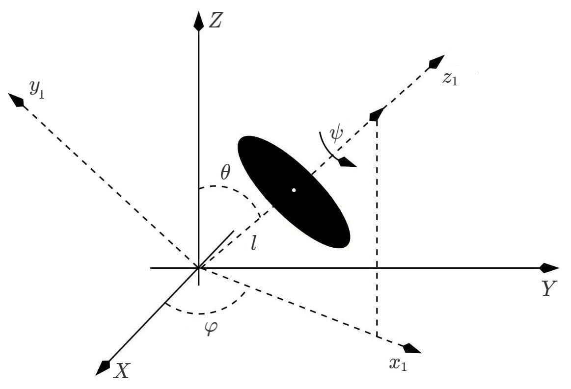
Figure 1 schematically shows a gyroscope, the mechanical motion of which is associated with rotation around its own axis, precession and nutation.

The Euler angles $$\psi$$, $$\varphi$$ and $$\theta$$ are used to describe the gyroscope motion. The angle $$\psi$$ describes the gyroscope rotation around its own axis, the angle $$\varphi$$ describes the gyroscope precession, and the angle $$\theta$$ describes the gyroscope nutation.
The Lagrange method was used to construct a mathematical model of gyroscope motion. The method allows obtaining differential equations of motion for the Euler angles. We used the approximation of the weightless axis and the absence of friction. The Lagrange function is the difference between the kinetic and potential energies of the gyroscope [3]:
$$L=\frac{I_{0}}{2} \left ( \dot{\theta}^{2} + \dot{\varphi}^{2} sin^{2}\theta \right ) $$ $$+$$ $$+\; \frac{I_{\psi}}{2} \left ( \dot{\psi} + \dot{\varphi} cos\theta \right )^{2} \! $$ $$-$$ $$-\; mgl cos\theta ,$$ $$(1)$$
where:
$$I_{0}$$ is the moment of inertia of the gyroscope about the $$x_{1}$$- and $$y_{1}$$-axes, perpendicular to the $$z_{1}$$-axis,
$$I_{\psi}$$ is the moment of inertia about the $$z_{1}$$-axis,
$$m$$ is the disk mass,
$$l$$ is the distance from the origin of coordinates to the disk.
The moment vector of the force is directed perpendicular to the directions of gravity and the axes $$z$$ and $$z_{1}$$. Hence [11]:
$$L_{\psi}=\frac{\partial L}{\partial \dot{\psi}}=I_{\psi} \left ( \dot{\psi} + \dot{\varphi} cos\theta \right )$$ $$=$$ $$ = const,$$ $$(2)$$ $$L_{\varphi}\!=\!\frac{\partial L}{\partial \dot{\varphi}}\!=\!\left (I_{0} sin^{2}\theta \! + \! I_{\psi} cos^{2}\theta \right )\! \dot{\varphi}$$ $$\! + \!$$ $$\! + \: I_{\psi} \dot{\psi} cos\theta$$ $$=$$ $$\: = const,$$ $$(3)$$
where:
$$L_{\psi}$$ is the angular momentum of the disk along the $$z_{1}$$-axis,
$$L_{\varphi}$$ is the angular momentum along the $$z$$-axis.
From equations $$(2)$$ and $$(3)$$ we obtain:
$$\dot{\varphi}=\frac{L_{\varphi}-L_{\psi} cos\theta}{I_{0} sin^{2}\theta},$$ $$(4)$$ $$\dot{\psi}=\frac{L_{\psi}}{I_{\psi}}-\frac{L_{\varphi}-L_{\psi} cos\theta}{I_{0} sin^{2}\theta} cos\theta.$$ $$(5)$$From the Euler-Lagrange equation, we obtain the third equation of motion [4]:
$$I_{0} \ddot{\theta}=-\frac{\left ( L_{\varphi}-L_{\psi} cos\theta \right ) L_{\psi}}{I_{0} sin\theta}$$ $$+$$ $$+\;\frac{cos\theta \left ( L_{\varphi}-L_{\psi} cos\theta \right )^{2}}{I_{0} sin^{3}\theta}$$ $$+$$ $$+\;mgl sin\theta$$ $$(6)$$Equations $$(4)\, -\,(6)$$ are differential equations of the gyroscope motion in the Euler angles representation.
[1] https://www.merriam-webster.com/dictionary
[2] Butikov E 2006 European Journal of Physics 27 1071
[3] Landau L.D. and Lifshitz E.M. 1976 Mechanics (New York: Pergamon Press)
[4] Marion J.B. and Thornton S.T. 1995 Classical Dynamics of Particles and Systems (Saunders College Publishing)

